Attuatori
Attuatore Elettrico SPS60E 48V per Pinne Vector™ V3-14/V4-15/V4-12HS
24/48V VDC
-


ANY SPEED
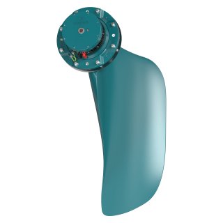
Sleipner's Vector Fins™ unique curved design comes with many benefits to improve the stabilization of your vessel.
The concave shape of the Vector Fins™ creates multilateral force direction improving the stationary positioning of a vessel while at-anchor. Tests at sea have proven that Vector Fins™ are up to 50% more efficient than standard flat fin stabilizer systems providing a safer and more comfortable boating experience.
The uniqueness of the concave shape also becomes evident while underway and only improves effectiveness as speed increases. By redirecting water forces in multiple directions at sea, tests have shown the Vector Fins™ are capable of reducing the uncomfortable rolling motion of the vessel by up to 95%.
-


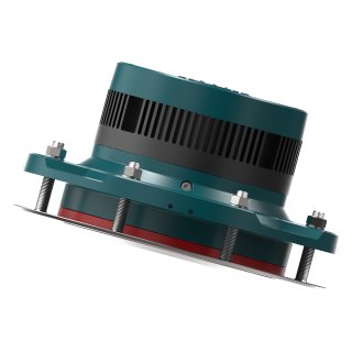
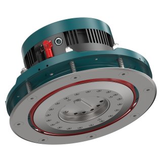
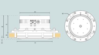
360° INSTALLATION
These products are designed to fit in small and challenging installation areas. Planning your product placement in the past has been complicated by finding the space or rotation required for the product's requirements. The unique cone shaft design allows you to utilize the space on board to install the actuators in any direction and insert the Vector Fins™ into the position you require.
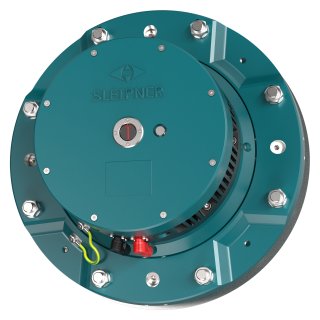
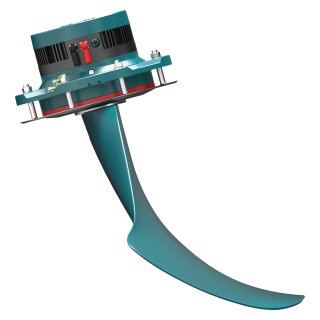
Codice Articolo: SPS60E-24/48V
L’attuatore SPS60E è il motore delle Sleipner Vector Fins™ su yacht nella gamma 19–24 metri. Combinando una compattezza senza pari con l’efficienza energetica, è facile da installare e si integra perfettamente con i sistemi degli yacht. L’SPS60E controlla con precisione il movimento delle pinne, riducendo al minimo il rollio e migliorando il comfort a bordo.
Alimentato a 24V o 48V DC, adatta continuamente la posizione delle pinne in tempo reale, garantendo una stabilizzazione ottimale per yacht di medie dimensioni che cercano prestazioni potenti con minimi requisiti di spazio.
Caratteristiche
ANY SPEED
Sleipner's Vector Fins™ unique curved design comes with many benefits to improve the stabilization of your vessel.
The concave shape of the Vector Fins™ creates multilateral force direction improving the stationary positioning of a vessel while at-anchor. Tests at sea have proven that Vector Fins™ are up to 50% more efficient than standard flat fin stabilizer systems providing a safer and more comfortable boating experience.
The uniqueness of the concave shape also becomes evident while underway and only improves effectiveness as speed increases. By redirecting water forces in multiple directions at sea, tests have shown the Vector Fins™ are capable of reducing the uncomfortable rolling motion of the vessel by up to 95%.
360° INSTALLATION
These products are designed to fit in small and challenging installation areas. Planning your product placement in the past has been complicated by finding the space or rotation required for the product's requirements. The unique cone shaft design allows you to utilize the space on board to install the actuators in any direction and insert the Vector Fins™ into the position you require.
-
A legacy that commits
We’ve lived and worked with the unruly sea for a hundred years. That’s why we develop important features that enables a boat to handle the sea better – that enable you to enjoy your boat, at anchor and at full speed. That is why you wanted a boat, isn’t it?
-
Beautiful engineering
The technology in our solutions is world-class. We know, because we’ve developed it ourselves, just as we manufacture every solution, and follow them until their fixed to a hull, ourselves. This meticulous attention to detail is why your day out always will be better with a Sleipner aboard.
-
Worldwide service
We take pride in our solutions’ function throughout their lifespan. So, we never really let them out of sight, even when they’ve left for distant shores. Our global network is there to ensure continuous optimal function. You know what you get with a Sleipner, today and tomorrow.